Maxxforce Dt Fuel System Diagram
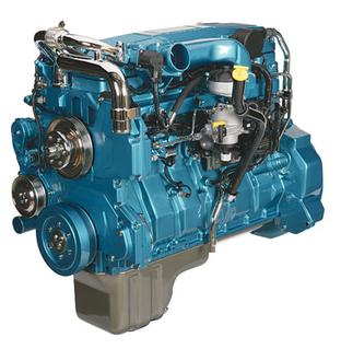
Maxxforce dt fuel system diagram. Changing the fuel filter on a 2012 international work star with an electric fuel pump. A backup is the action of saving the content of your important ebook into files that you store. MaxxForce DT MaxxForce 9 and 10 119 mm 468 in 146 mm 575 in Compression ratio MaxxForce DT MaxxForce 9 and 10 169.
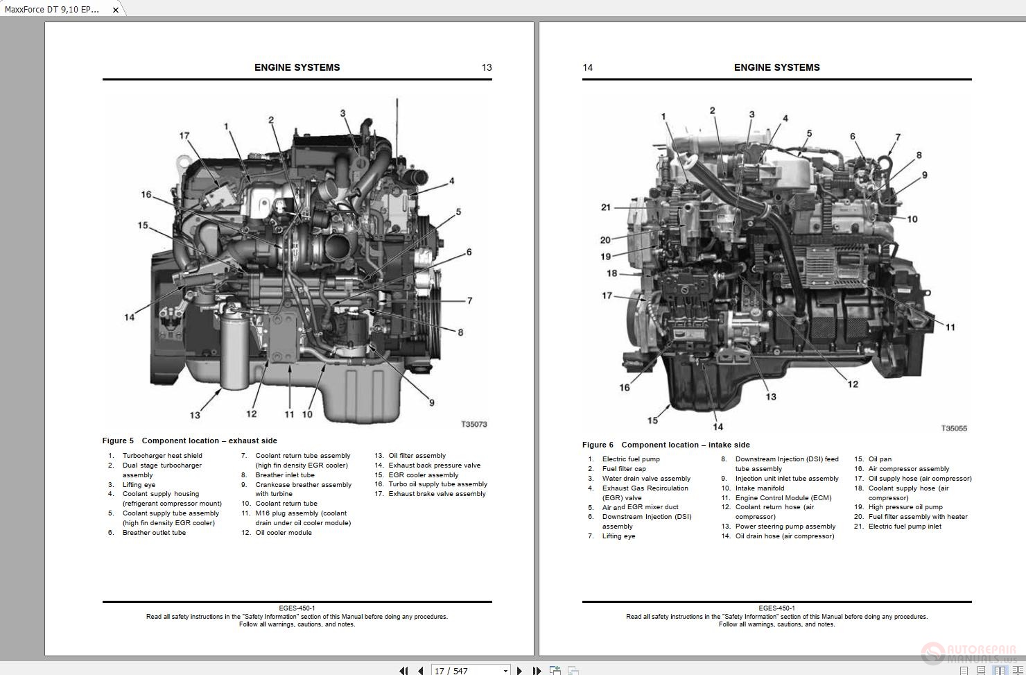
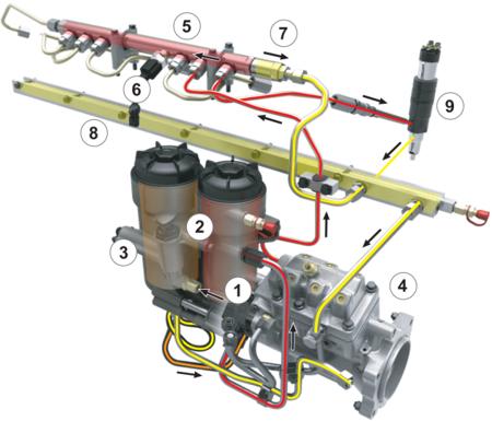
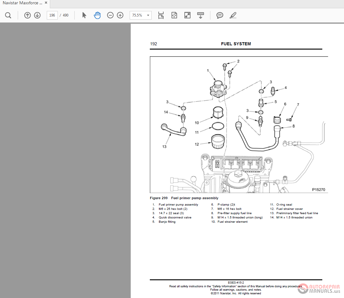
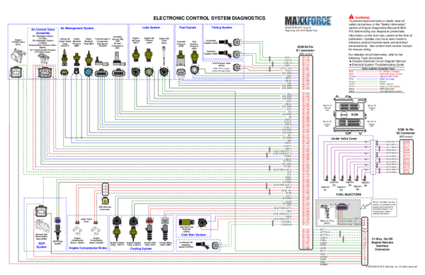
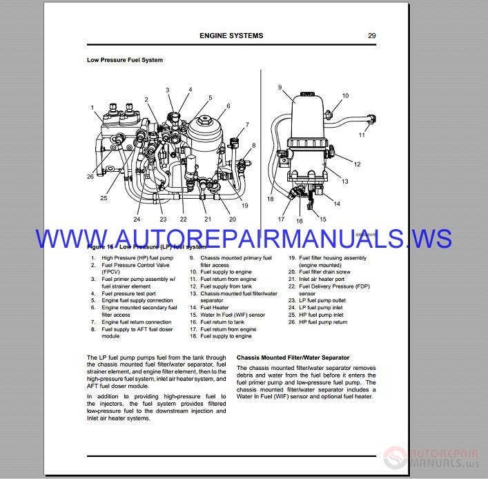
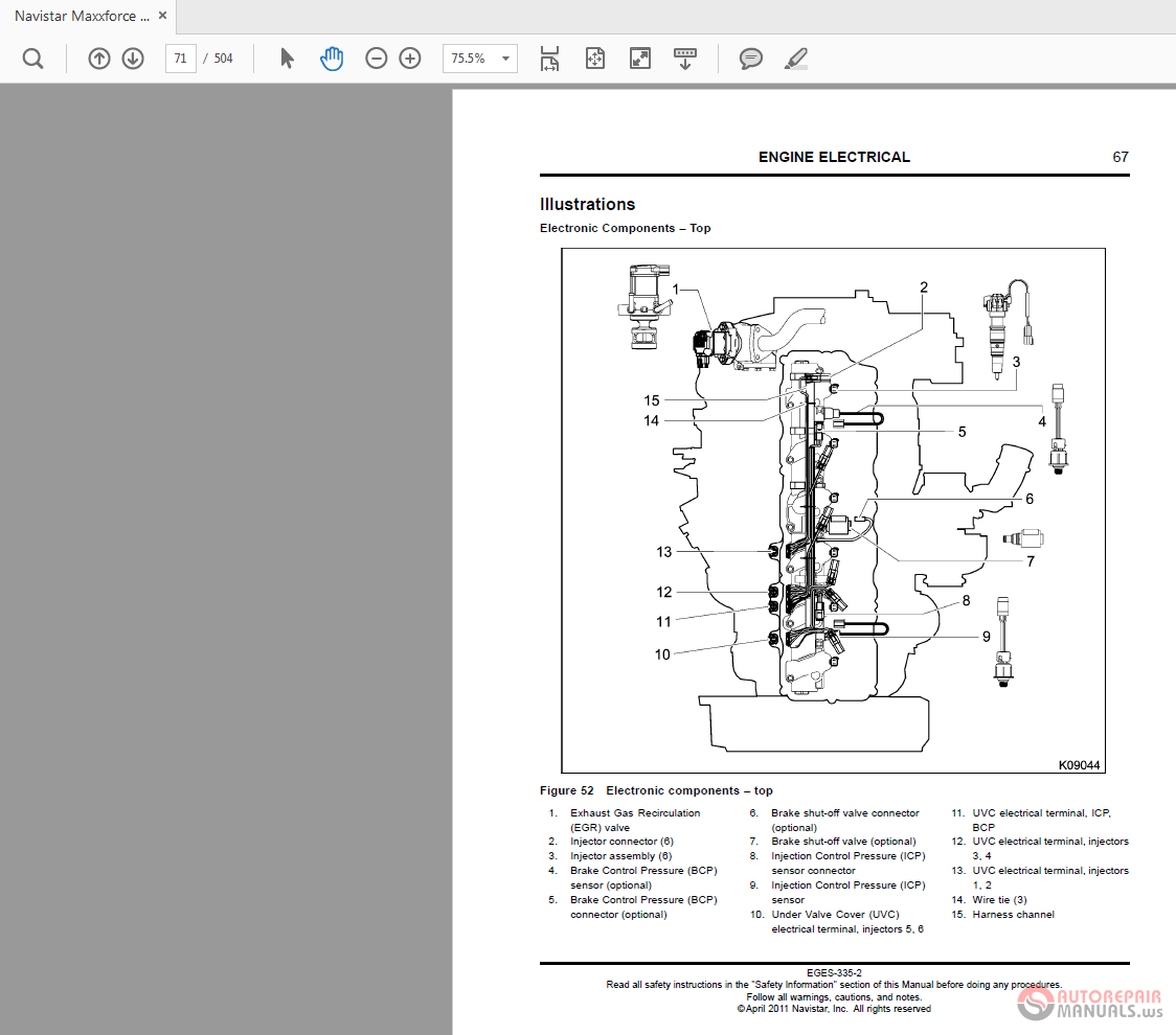
EPA 2010 and later DT 9 10 engines use a fuel module that incorporates many features including an electric fuel pump fuel heater and fuel strainer. MaxxForce DT 9 10 2010 - 2013 Engine Wiring Diagram Page 2 of 3 86-Pin Connector 6341 53-Pin Connector 6340 Twisted pair Red B Battery Voltage Red High side driver control Blue VREF 5 Volts Green Green AC Speed Signal Signal Brown Data Communication Black Black Purple Injectors GND Ground Low side driver control Color code for schematic lines. 2011 maxxforce dt EPA 07.
FuelFilterModuleDrain The fuel filter module drain is used to drain the module of water or contaminants. Lubrication System Fuel Filter and Oil Pan The oil filter for the 2010 MaxxForce 7 engine is located at the bottom of the engine. -The fuel strainer can be seen when the pump is removed from the filter module.
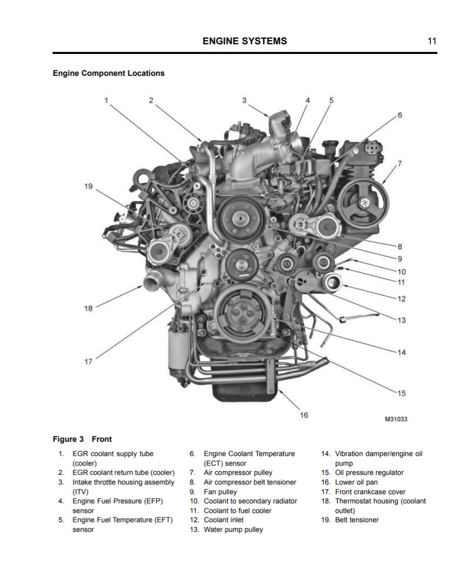
95 Egr Valve For 2011-2013 International 7600 Maxxforce 13 International C259tx Maxxforce dt fuel system diagram D. This configurationprovides improved performance and reduces emissions. Set up DVOM to measure DC voltage.
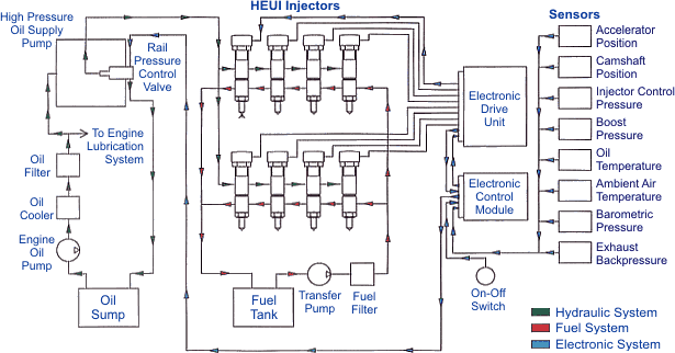
International Maxxforce 13 High Pressure Fuel Pump remove and replace. - The fuel strainer can be seen when the pump is removed from the filter module. The system includesanunder-valve-coverhigh-pressureoilmanifoldfuel injectors andahigh-pressureoilpump.
The pan is cast aluminum. ENGINE SERVICE MANUAL Foreword Technical Service Literature Navistar Inc. Includes color coded wiring connector pinouts and a table of values for diagnostic purposes engine only.
4045 45L and 68L Level 11 Electronic Fuel System with Denso HPCR 4045 68L - Level 4 Electronic Fuel System with Bosch VP44 Injection Pump 4045 Level 34 4045 PowerTech Final Tier 4-Stage IV 4045 PowerTech Interim Tier4-Stage III B 6068 PowerTech Interim Tier 4-Stage III B 174hp 6090 PowerTech Final Tier IV Stage IV. NAVISTAR 50 T444E A T S TS ngine ComponentsE.
Cat 70 Pin Ecm Wiring Diagram Pdf.
IMPORTANT NOTICE High pressure fuel system issues have been directly linked to the high pressure fuel pump harness 7080246C91 click here for identifiers. 1 Aspiration VGT turbocharged and Charge Air Cooled CAC Rated power rpm1 MaxxForce DT MaxxForce 9 MaxxForce 10 245 bhp 2600 rpm 310 bhp 2200 rpm 310 bhp 2200 rpm Peak torque rpm1 MaxxForce DT MaxxForce 9. Fuel System Aug 01 2021 DuraStar ProStar MaxxForce 2007 international 4300 how to pull codes and clear them. This document will guide the user through step based diagnostics and snapshot analysis for the High Pressure Fuel System concerning the DTC 3055. NAVISTAR 50 T444E A T S TS ngine ComponentsE. A backup is the action of saving the content of your important ebook into files that you store. 1 of 2 Videos. Lubrication System Fuel Filter and Oil Pan The oil filter for the 2010 MaxxForce 7 engine is located at the bottom of the engine. 95 Egr Valve For 2011-2013 International 7600 Maxxforce 13 International C259tx Maxxforce dt fuel system diagram D.
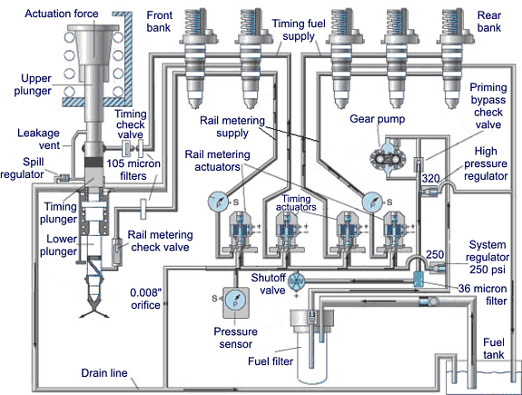
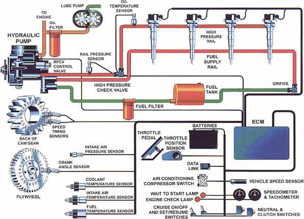
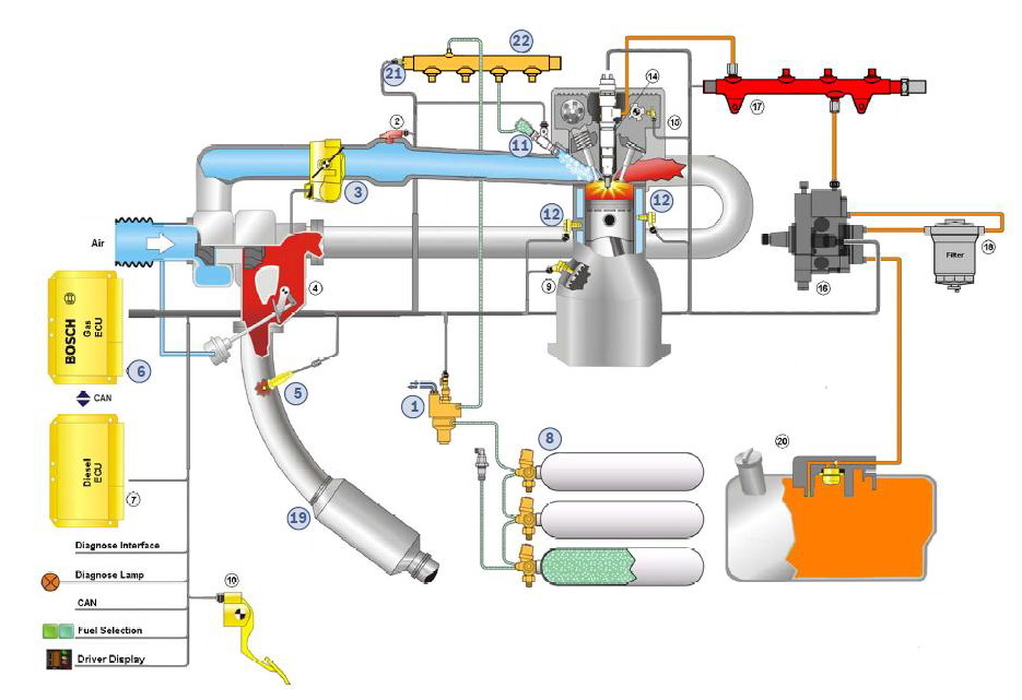
Maxxforce dt fuel system diagram. The fuel injection system is electro-hydraulic. The ECM electronically controls the injectors which allows multiple injections and more precise fuel delivery to improve combustion emissions and cold-start performance. The throttle valve is used to increase the efficiency of the after treatment systems soot reduction process. IMPORTANT NOTICE High pressure fuel system issues have been directly linked to the high pressure fuel pump harness 7080246C91 click here for identifiers. In an effort to give beneficial advice to our followers we have aimed to obtain the nearest relevance image about fuel system diagram on dte And here you will observe now this picture. International Maxxforce 13 High Pressure Fuel Pump remove and replace.
















Post a Comment for "Maxxforce Dt Fuel System Diagram"